AC VOLTAGE APPLIED TO AN INDUCTOR
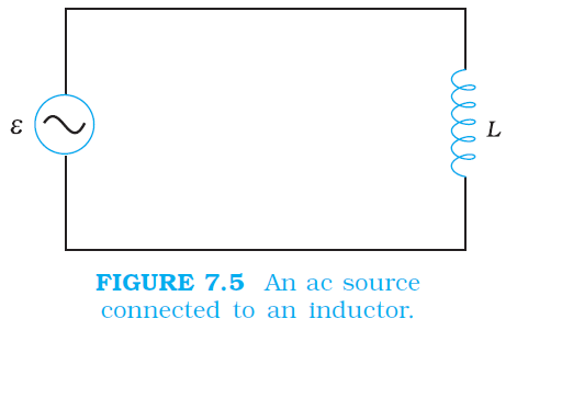
`color{blue} ✍️` Figure 7.5 shows an ac source connected to an inductor.
`color{blue} ✍️`Usually, inductors have appreciable resistance in their windings, but we shall assume that this inductor has negligible resistance. Thus, the circuit is a purely inductive ac circuit. Let the voltage across the source be `v = v_m sin omega t.` Using the Kirchhoff’s loop rule `sum epsilon(t) = 0` and since there is no resistor in the circuit,
`color{blue} ✍️` where the second term is the self-induced Faraday emf in the inductor; and `L` is the self-inductance of the inductor. The negative sign follows from Lenz’s law (Chapter 6).
Combining Eqs. (7.1) and (7.10), we have
`color{blue} ✍️` Equation (7.11) implies that the equation for i(t), the current as a function of time, must be such that its slope `di//dt` is a sinusoidally varying quantity, with the same phase as the source voltage and an amplitude given by `vm//L.` To obtain the current, we integrate `di//dt` with respect to time:
`color{purple}{int(di)/(dt) dt = (v_m)/L int sin(omega vt)dt}`
`color{blue} ✍️` and get,
`color{purple}{i = - (u_m)/(omega L) cos (omega t) +}` constant
`color{blue} ✍️`The integration constant has the dimension of current and is time independent. Since the source has an emf which oscillates symmetrically about zero, the current it sustains also oscillates symmetrically about zero, so that no constant or time-independent component of the current exists. Therefore, the integration constant is zero. Using
`color{purple}{- cos (omega t) = sin (omega t- (pi)/2)}` .
`color{blue} ✍️` we have
`color{blue} ✍️` where `i_m= (v_m)/(omega L)` is the amplitude of the current. The quantity `omega L` is analogous to the resistance and is called inductive reactance, denoted by `X_L;`
`color{blue} ✍️` The amplitude of the current is, then
`color{blue} ✍️`The dimension of inductive reactance is the same as that of resistance and its SI unit is ohm `(Omega).`
The inductive reactance limits the current in a purely inductive circuit in the same way as the resistance limits the current in a purely resistive circuit. The inductive reactance is directly proportional to the inductance and to the frequency of the current.
`color{blue} ✍️`A comparison of Eqs. (7.1) and (7.12) for the source voltage and the current in an inductor shows that the current lags the voltage by `p/2` or one-quarter (1/4) cycle. Figure 7.6 (a) shows the voltage and the current phasors in the present case at instant `t_1`.
The current phasor I is `pi//2` behind the voltage phasor `V`. When rotated with frequency `omega` counterclockwise, they generate the voltage and current given by Eqs. (7.1) and (7.12), respectively and as shown in Fig. 7.6(b).

`color{blue} ✍️` We see that the current reaches its maximum value later than the voltage by one-fourth of a period `[T/4= (pi//2)/omega]` You have seen that an inductor has reactance that limits current similar to resistance in a dc circuit.
Does it also consume power like a resistance? Let us try to find out.
The instantaneous power supplied to the inductor is
`color{purple}{P_L = iv= i_m sin(omegat- pi/2)xxv_m sin(omegat)}`
`color{purple}{= (i_mv_m)/2 sin (2omega)}`
`color{blue} ✍️` So, the average power over a complete cycle is
`color{purple}{P_L (-(i_mv_m)/2 sin(2omegat))}`
`color{purple}{= - (i_mv_m)/2 (sin (2omega t))}`
`color{blue} ✍️` since the average of sin `(2 omega t)` over a complete cycle is zero.
Thus, the average power supplied to an inductor over one complete cycle is zero.
Figure 7.7 explains it in details.
.png)
`color{blue} ✍️`Usually, inductors have appreciable resistance in their windings, but we shall assume that this inductor has negligible resistance. Thus, the circuit is a purely inductive ac circuit. Let the voltage across the source be `v = v_m sin omega t.` Using the Kirchhoff’s loop rule `sum epsilon(t) = 0` and since there is no resistor in the circuit,
`color{blue}{v - L (di)/(dt) = 0}`
...........(7.10)`color{blue} ✍️` where the second term is the self-induced Faraday emf in the inductor; and `L` is the self-inductance of the inductor. The negative sign follows from Lenz’s law (Chapter 6).
Combining Eqs. (7.1) and (7.10), we have
`color{blue}{(di)/(dt) = v/L = (v_m)/L sin omega ct}`
............(7.11)`color{blue} ✍️` Equation (7.11) implies that the equation for i(t), the current as a function of time, must be such that its slope `di//dt` is a sinusoidally varying quantity, with the same phase as the source voltage and an amplitude given by `vm//L.` To obtain the current, we integrate `di//dt` with respect to time:
`color{purple}{int(di)/(dt) dt = (v_m)/L int sin(omega vt)dt}`
`color{blue} ✍️` and get,
`color{purple}{i = - (u_m)/(omega L) cos (omega t) +}` constant
`color{blue} ✍️`The integration constant has the dimension of current and is time independent. Since the source has an emf which oscillates symmetrically about zero, the current it sustains also oscillates symmetrically about zero, so that no constant or time-independent component of the current exists. Therefore, the integration constant is zero. Using
`color{purple}{- cos (omega t) = sin (omega t- (pi)/2)}` .
`color{blue} ✍️` we have
`color{blue}{t = t_m= sin (omega t- (pi)/2)}`
...........(7.12)`color{blue} ✍️` where `i_m= (v_m)/(omega L)` is the amplitude of the current. The quantity `omega L` is analogous to the resistance and is called inductive reactance, denoted by `X_L;`
`color{blue}{X_L = omega L}`
............(7.13)`color{blue} ✍️` The amplitude of the current is, then
`color{blue}{i_m = (v_m)/(X_L)}`
..........(7.14)`color{blue} ✍️`The dimension of inductive reactance is the same as that of resistance and its SI unit is ohm `(Omega).`
The inductive reactance limits the current in a purely inductive circuit in the same way as the resistance limits the current in a purely resistive circuit. The inductive reactance is directly proportional to the inductance and to the frequency of the current.
`color{blue} ✍️`A comparison of Eqs. (7.1) and (7.12) for the source voltage and the current in an inductor shows that the current lags the voltage by `p/2` or one-quarter (1/4) cycle. Figure 7.6 (a) shows the voltage and the current phasors in the present case at instant `t_1`.
The current phasor I is `pi//2` behind the voltage phasor `V`. When rotated with frequency `omega` counterclockwise, they generate the voltage and current given by Eqs. (7.1) and (7.12), respectively and as shown in Fig. 7.6(b).
`color{blue} ✍️` We see that the current reaches its maximum value later than the voltage by one-fourth of a period `[T/4= (pi//2)/omega]` You have seen that an inductor has reactance that limits current similar to resistance in a dc circuit.
Does it also consume power like a resistance? Let us try to find out.
The instantaneous power supplied to the inductor is
`color{purple}{P_L = iv= i_m sin(omegat- pi/2)xxv_m sin(omegat)}`
`color{purple}{= (i_mv_m)/2 sin (2omega)}`
`color{blue} ✍️` So, the average power over a complete cycle is
`color{purple}{P_L (-(i_mv_m)/2 sin(2omegat))}`
`color{purple}{= - (i_mv_m)/2 (sin (2omega t))}`
`color{blue} ✍️` since the average of sin `(2 omega t)` over a complete cycle is zero.
Thus, the average power supplied to an inductor over one complete cycle is zero.
Figure 7.7 explains it in details.